Cover article
published in September, 2002 QST
© 2002 by the ARRL
Download
Free ARRL Antenna Mechanical Design Spreadsheets
This
article is not a reprint of the QST manuscript. Corrections
and additional information not present in the original article
are here.
L.B. Cebik, W4RNL, (SK) ARRL Technical Adviser, and antenna authority reviewed this QST article before publication. I worked with him to clarify and complete some areas.
In an email to ARRL headquarters, he summarized this manuscript. He said that he read the article with great interest. Although he thought it was not too technical, he did emphasize that "... this was the best information on this type of antenna that the ARRL had ever received in their (at that time) 90-year history."
Cebik further stated that my antenna hardware designs were "...somewhat rough and ready." Indeed. I like them to last.
All of the antennas in this photo are my designs.
The entire tower and antenna installation was done solely by me, with zero assistance from anyone. No crane, no ground crew. I did all of of this stuff by myself using only an electrical winch with a 100-foot long control pendant.

Practical
High Performance
HF Log Periodic Antennas
In this article, K8CU describes the electrical and mechanical
design process for two LPs that cover the HF bands from 10-30
MHz.
How
do you go about achieving good DX performance on all HF amateur
bands from 10 to 30 MHz without using separate antennas for
each band? One alternative that occurred to me was the log periodic
(LP) antenna. Although I thought that the penalty for using
this type of antenna was poor front-to-back (F/B) ratio and
forward gain when compared to other antennas, I decided to take
a closer look.

"...the
antenna isn't one of the important things in an amateur station,
it is the ONLY thing..."
Electrical
Design
I had used three-element monoband Yagi antennas for years and
considered them to be good DX antennas, so I chose that design
as the performance standard for comparison. Using modeling software,
I tested several log periodic antennas of six to eight elements
with boom lengths of 16 to 20 feet. The software confirmed that
these antennas were inferior, just as I expected. I wondered
if more elements and a longer boom would work better and found
that longer boom log periodic antennas with more elements work
much better.
The
antenna modeling software I used for this project is NEC-WIRES,
NEC-2 based software from K6STI [1], and Nec-Win Plus+, a Windows-based
product from Nittany Scientific [2]. If you choose to use other
software to model log periodic antennas, make sure the software
will correctly model the phasing transmission line that runs
down the center of the boom and connects each element together. NEC-2 antenna models use the "TL" (transmission line) facility
for modeling, which produces a non-radiating, lossless mathematical
transmission line for the model.
The
quantity of model segments for the elements is odd so that the
phasing line is centered. The number of segments per wire is
stepped in accord with the wire length and is the nearest odd
integer to a calculated number. Starting with eleven segments
for the shortest element, longer elements have progressively
more segments for the best possible alignment of segment junctions.
The NEC-2 antenna file is available and may be down loaded and
then imported into your design software:
*.ANT for the VOA Export File
*.NWP for the Nittany NEC-win Plus+
*.NEC for the NEC file
I tested dozens of various log periodic arrays--from very small
ones to those with impractical long booms. As the boom length
and number of elements increased, the front-to-back ratio (F/B)
became respectable. My eventual antenna design had about the
same characteristics of a three-element monoband antenna, with
the advantage of a single feed line.
Some log periodic antennas have reduced performance at each
end of the desired frequency span. This is because few elements
are active at the frequency extremes to provide good gain and
F/B. Some antenna designers have resorted to using passive reflectors
or directors to boost performance. I tried to modify the antenna
element spacing and lengths of traditional log periodic designs
and was able to successfully optimize the antenna to give good
14-30 MHz performance without requiring additional passive elements.
The optimized antenna has 13 elements and a boom length of about
38 feet.

3D radiation
pattern of log periodic antenna
I
still wanted 30-meter coverage, so I created a second antenna
by adding two more elements, lengthened the boom, and optimized
again for the 30-meter band. The new design had a boom length
of 48 feet. 30-meter performance was down somewhat from the
standard 3-element monoband antenna--within 1/2 dB in forward
gain and a good F/B of 20 dB. Since only two elements were added
to give this additional coverage, I decided that reduced forward
gain was acceptable.
Sweeping the design frequency in steps of 100 kHz and tabulating
the results across the entire operating bandwidth resulted in
the gain and F/B plots shown in Figure
1 and Figure 2. It's
interesting to note the 30-meter performance of the antenna.
Only two elements have been added to give coverage for this
band, but the forward gain falls midway between that of a two
and three element monoband Yagi. F/B is 20 dB, which is 8 dB
better than a two-element monoband Yagi and almost as good as
a full-sized three-element Yagi at 25 dB.
A recently published article [3] stated that all elements in
a log periodic antenna are active at all frequencies. All elements
are active forward of the one most active at any given frequency.
Figure 9 shows a modeling software graphic of element current
magnitudes when the array is operating at 10.1 MHz. Significant
element current at this frequency is present on some elements
other than the two added for 30-meters. This makes sense and
explains the improved 30-meter performance.
Figure
9
Another improvement to 10 MHz performance resulted from adding
a shorted stub to the rear element. This consists of an electrical
length (100% velocity factor) of 78.74 inches of 450 Ohm open-wire
transmission line connected to the rear element's antenna terminals
with the far end shorted. To get the physical length, multiply
this by the line's velocity factor. Adding the stub improves
F/B ratio on 30-meters, the band on which the rear element has
the most effect, by 9 dB without significant effect on gain
or SWR on the other bands. As constructed, the stub is coiled
up and attached to the boom with acceptable results. To eliminate
interactions in the coiled line or with the boom pipe, the best
solution would be to use a lightweight extension of 1-inch diameter
PVC pipe fastened to the boom using stainless hose clamps, with
the ladder line then taped to the PVC pipe. The resulting pattern
and SWR response makes a nice 30-meter antenna.


The
main feed point impedance of both antennas is 200 Ohms. I matched
this value to 50 Ohm coaxial line using a homemade broadband
4:1 toroidal balun suitable for legal limit power operation.
Mechanical Design
NEC-2
antenna design software uses a single wire of a constant diameter
for each element to calculate antenna characteristics. Since
most HF antennas require elements of tapering size, a conversion
method is required. I used a spreadsheet template from Dave
Leeson, W6NL's, Yagi design book [4] which calculates the conversions
from practical elements to their theoretical equivalents. The
spreadsheet is constructed with multiple columns--one column
per element section. Element section diameters, wall thickness,
and lengths are entered. The software does more than just tapered
element conversion. Antenna element weight, wind speed survival,
ice loading characteristics, and more are calculated as you
design each element. Many of Leeson's ideas for Yagi antenna
physical design in this book apply directly to log periodic
antennas. Reading this book and applying the mechanical design
fundamentals along with using the software is recommended without
hesitation. Using it, you can make mechanically reliable antennas
that perform electrically as intended.
Another spreadsheet template is entitled "Calculation of Element
Strength and Equivalent Length" which calculates the wind speed
survival of an element. My county in Ohio has a 70 MPH requirement
[5]. Enter the physical tubing diameters and lengths for the
element, adjusting the lengths of each tapered section to keep
the calculated reactance as close to 0 W as possible. (When
the spreadsheet shows a low reactance, the tapered element is
equivalent to the NEC-2 single diameter length.) If the wind
speed survival of each element section is at or above your required
wind speed survival, and the element section is practical to
build, you are done. If not, increase the diameter, wall thickness,
or shorten the lengths of individual element sections (always
keeping the reactance near zero) until the element design will
survive at the required wind speed. High wind speed survival
speeds are relatively easy for the shorter elements. Those in
the 14 MHz range and below require more care.
Once each element is designed, the weight and area calculations
of each are then used in another spreadsheet that calculates
boom survival characteristics in a similar way. Start with individual
elements, and then work on the boom and boom guys.
The
advantage of this spreadsheet technique is simplicity and speed.
You are only working on one element (or boom) at one time, and
the spreadsheet runs very quickly, even on older computers.
The spreadsheets are provided in Lotus 1-2-3 format (WKS) and
will work with practically any spreadsheet program, such as
Borland / Corel Quattro Pro™ or Microsoft EXCEL™.
This algorithm for tapered element conversion is summarized
in the ARRL Antenna Book [6].
Construction
The
center section of the 10 MHz and the 14-30 MHz elements are
different because the larger 10 MHz elements are 50 feet long
and require a heavier boom to element mounting method. The tubing
diameter of the 14-30 MHz elements is all standardized at an
initial 1-inch diameter, while the two 10 MHz elements start
out at 2-inches. Each element type has a standardized construction
method. All use the same tubing diameters and initial lengths,
then taper in a uniform fashion. The individual element's final
tip length then determines the resonant frequency. The table
of element tubing sizes and dimensions are shown in Table
1. Note that these dimensions are for the exposed lengths
of tubing visible after assembly. Four inches of tubing overlap
are required for assembly where a smaller tube fits closely
into the next larger tube.
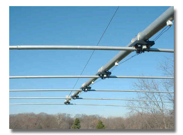 Center Element Detail - Notice
Homemade 325 Ohm Transmission Line
Center Element Detail - Notice
Homemade 325 Ohm Transmission Line The
larger antenna may be built from the smaller one by just adding
a boom extension and two elements. With one exception, the element
lengths and boom spacing on the smaller antenna remain the same
when the larger antenna components are added. The boom position
of the largest element on the smaller antenna moves 10 inches.
More details of these changes and the element layout are shown
in Figure 4.
A log periodic antenna requires each element center to be split
and insulated from the supporting boom. The insulating center
for the large 2-inch elements is a solid rod of PVC, UHMW, or
similar insulating material, 1.875 inches in diameter and 12
inches long. One rod is required for each of the two larger
elements note [7]. Since this isn't a standard diameter, it
will be necessary to turn a larger diameter rod to this size
using a lathe. Most machine shops can handle this job for you.
Use a section of 2-inch diameter aluminum tubing to verify proper
fit. Thanks to George Crego, WD8ATX, for his expert lathe work
in making my insulators. The mechanical drawing for the larger
two-inch 10 MHz element is shown in Figure
5.
The
boom guy detail of Figure 5
shows how 0.25" thick 3-inch aluminum angle is used as the basis
for the boom guy anchors. Galvanized 1-inch closed-end eyebolts
are attached to the aluminum angle, which is attached to the
boom using one McMaster #8896T57 3-inch stainless U-bolt clamp.
One U-bolt is required for each boom guy. Two identical U-bolts
are also used to attach the 2-inch element mounting bracket
to the boom.
Surrounding the aluminum element is a 12-inch long piece of
schedule 40 PVC pipe with a 1/4-inch slit cut lengthwise in
it. This allows the PVC pipe to compress securely around the
aluminum element. A pair of ¼" x 20 x 2.5-inch long stainless
steel machine screws with double nuts serve as terminals to
connect the phasing transmission line. This assembly is then
mounted using four McMaster # 3042T57 stainless U-bolts on a
support plate made of 3-inch aluminum angle, 8-inches long.
These two larger elements are about 50 feet long, and this mounting
arrangement has proven to be trouble-free. All elements are
mounted below the boom.
The insulating center for the smaller 14-30 MHz elements was
originally made with a custom designed UHMW polyethylene block
with an integral ultraviolet light inhibitor that has worked
well in this application. To make it easier for others to duplicate
this antenna design, I have redefined the elements to now use
commercially available components [8].
The mechanical drawing for the smaller 14-30 MHz element is
shown in Figure 6. The construction
method for the smaller elements uses similar, but smaller components.
A 7/8-inch diameter solid fiberglass rod fits inside the two
1-inch diameter aluminum element ends. One-inch PVC pipe with
a 1/4-inch slot cut lengthwise fits around each tubing end.
This assembly is supported by two aluminum saddles that mount
on a flat 1/4-inch thick aluminum plate which measures 8 x 3.5
inches. Stainless machine screws with double nuts serve as the
element electrical terminals. The entire element plate assembly
is held to the boom using two McMaster # 8896T57 stainless U-bolts.
Closed-end 1/8-inch aluminum pop rivets are used to join the
overlapping tubing sections together. Two were used to join
the smallest sizes, while eight were used for the largest. Just
prior to assembly, coat the overlapping area with a thin coating
of aluminum joint compound (Penetrox or equivalent) to inhibit
corrosion between the aluminum tubing sections. Stainless or
galvanized hardware is used throughout, not just on the electrical
connections.
I chose a boom diameter of three inches for both antennas. The
mechanical properties of this boom were tested using the mechanical
design template from W6NL's book. Boom guys are necessary to
keep the boom straight. I checked for possible interaction between
the metal boom guy wires and the elements using the NEC-2 design
software. No problems were discovered, probably because the
guys are parallel to the boom and at a right angle to the elements.
This eliminates the need for Kevlar guy cable. For these antennas,
3/16-inch EHS guy wire works well. Use the mating grips for
clean and good looking boom guys.
The
booms are 6061-T6 aluminum, 3-inch OD x 0.125-inch wall. I used
two 24-foot pieces of 3-inch diameter aluminum pipe for the
48-foot boom. The 38-foot boom was made with a 24-foot piece
joined to a 14-foot piece. I connected both boom pieces together
using a larger outside pipe as a coupler between each section.
The boom coupler is made of a 2-foot length of 6061-T6 schedule
40 aluminum pipe which is 3.5-inch OD x 0.216-inch wall. Pipe
doesn't fit closely like tubing does, but the joint was close
enough to be practical. I considered using .025-inch thin metal
shims to make up for the somewhat loose connection, but it wasn't
necessary. Use two 2 x 13 x 5 inch galvanized bolts at right
angles through the entire boom joint to secure the boom splice
section to each boom end. Four boom bolts are required for each
antenna. Alternately, consider making a 24-inch long solid center
internal boom splice. This would be somewhat harder to drill
through for the boom bolts, but it would result in a cleaner
design. It would require machining on a lathe to make it fit
the inside diameter of the main boom.
Any
boom sag resulting from a slightly loose boom joint is removed
when the boom guys are tightened. Boom guy tension is determined
by hanging the antenna at the center of gravity from a cable.
With the antenna elements level, sight along the boom and adjust
the turnbuckles until it looks straight. The larger 48-foot
boom requires four boom guys, while the 38-foot version needs
only two. Once in the air, the perfectly straight boom looks
great and it stays that way. The mechanical drawing for the
boom couplers and vertical guy support is shown in
Figure 7. An alternative to the boom support and tower to
boom plate is commercially available [8].
Make
sure to align the eyebolt holes in the vertical boom support
to be directly over the boom. This will prevent the boom from
bowing when the turnbuckles are adjusted. Two 1/2-inch by 12-inch
galvanized turnbuckles are used for the 38-foot boom antenna.
The 48-foot boom version requires four turnbuckles and eye bolts.
The vertical boom support is fabricated from a single 2-foot
length of 1/4-inch thick, 3-inch aluminum angle.
The
characteristic impedance of the element phasing transmission
line is 325 ohms. This value was chosen for best SWR performance
as shown in Figure 8. The
measured results agree closely with this graph. I made this
using 14-gauge solid copper wire with a spacing of 1/2-inch.
I made small insulating standoffs from a plastic block and supported
the wires every 18 inches along the boom. Keep the wire spacing
close to the desired 1/2-inch spacing and support the phasing
line an inch from the boom. To make this phasing line easier
to fabricate, consider using commercially available high power
300-Ohm twin lead [9]. Don't use the common TV variety or the
commonly available 450 Ohm open-wire line. Remember to alternately
connect each element center 180 degrees out of phase with the
next element by flipping the twin lead one-half turn between
elements. Repeat this phasing procedure for all elements. Keep
the phasing line spaced an inch from the boom.
The feed-point balun is made using 11 bifilar turns of 14 gauge
Teflon-covered wire wound on a relatively low permeability F240-67
ferrite core that fits inside a PVC pipe for weather resistance
[10]. Commercial alternatives are also available [11].
The two antennas were mounted on a 100-foot tall RTS rotating
tower made of Rohn 55 tower sections. On 14-30 MHz I have a
stacked array of the two antennas, with the 48-foot boom antenna
at a height of 88 feet, and the 38-foot boom antenna at a height
of 44 feet, for a separation of 44 feet. (See
stacking notes). On 30 meters, I have a single gain antenna
at a height of 88 feet. Tower guy wire placement prevented the
stacking of two identical larger antennas. The boom-to-tower
mount is a flat aluminum plate 24 x 12 x 0.25 inches thick.
The antenna mounts to it using four 3.5-inch U-bolts that fit
around the boom section coupling. The plate is secured to the
tower using U-bolts that fit the Rohn 55 tower legs. A similar
plate could be used to make a mount for a single vertical mast
[12]. A homemade bottom-both-upper
antenna switch using vacuum relays and a stack matching
network allows flexible antenna switching.

Material Sources
The
best sources I have found for the aluminum tubing elements are
the advertisers in QST. They were cheaper than a local supplier,
and they had all sizes necessary for these antennas. I have
had good luck using the 6083 alloy. The six-foot sizes required
for these antennas may be shipped by UPS. I found the long aluminum
pipes for the boom at a local supplier. It costs a lot to ship
this material, so look for it locally first. The stainless U-bolt
hardware may be hard to find locally. Specific U-bolts used
in these antennas are identified on the mechanical drawings
with the supplier's part number. Other sources may be helpful
in supplying these and other necessary parts.
Conclusion
I'm
happy with these antennas since they meet my design objective.
The performance of the large antenna on 30-meters has been gratifying.
Prior antennas on this band were dipoles or verticals. Going
to a gain antenna with a good F/B was a pleasant change.
These
antennas have been in service since 1995. No problems have since
developed, due in part to the mechanical design method and conservative
construction. No maintenance of any kind has been necessary.
Electrical performance has been very good, and the flexible
stack arrangement and independent antenna selection have proven
to be useful.
Notes
1.
K6STI Brian Beezley k6sti@n2.net
[No longer sold]
2. Nittany Scientific www.nittany-scientific.com
3. L.B. Cebic, W4RNL, "Notes on Standard Design LPDAs for 3-30
MHz PT2: 164-Foot Boom Designs" QEX, July/August 2000, p 17.
4. David B. Leeson, W6QHS, "Physical Design of Yagi Antennas",
1992. This book and software are available from the ARRL. The
book is ARRL # 3819. The software on floppy disk is available
separately as #3827 IBM PC or #3843 Macintosh. As a convience
to readers of this article, permission to download this software
(in IBM PC format) has been granted by the ARRL. To download
this software, click here.
5. Ibid, Figure 2-3 Page 2-8. My tower installation was independently
evaluated by a registered PE who also used this local wind speed
number.
6. R. Dean Straw, ed., The ARRL Antenna Book, 18th Ed. (Newington:ARRL,
1997), pg 2-15.
7.
Aluminum tubing, guy wire, guy grips, and turnbuckles are available
from Texas Towers
8. A suitable commercial choice is Harbach stainless saddle
clamps available from DX
Engineering Their SAD 125 clamps can be used as insulated
supports as described in this article. They also offer special
insulated supports. The DX Engineering 3-inch boom support and
tower to boom plate both appear to be useful as well. Specific
U-bolt part numbers are those of
McMaster-Carr Supply Co They also have the PVC rod used
for two of the element insulators, closed end aluminum pop rivets,
solid fiberglass and UHMW rod, eyebolts, tubing plastic end
caps, and general stainless and galvanized hardware. 2-inch
diameter, solid UHMW rods are sold by McMaster-Carr Supply in
one-foot increments as their part number 8701K49. Another source
for the solid fiberglass rod is Max
Gain Systems
9. High power 300 ohm #18 ladder line (#562) is available from
The RF Connection This is
19 strands of Cu-clad with poly jacket.
10. Jerry Sevick, W2FMI, "Transmission Line Transformers" ARRL,
1987, section 8-3.
11. An assembled high power 4:1 balun is available from
Amidon as part number W2FMI 4:1-HBHT200.
12. The ARRL Antenna Book chapter on construction and antenna
materials contains alternative construction methods and many
helpful hints on other related topics. Aluminum tubing specifications,
element assembly, element clamping techniques, tips on antenna
longevity and more are discussed in detail.
Get single file download of all available mechanical drawings.

Frequently
Asked Questions
Question
- I have a question about element size here in my country. We
do not have the same sizes for the elements. Our tubing sizes
are metric: (All in mm). So this is what I can build with, does
a different size change the element lenghts?
|
Outside
Diameter |
Inside
Diameter |
Wall
Thickness |
|
50 |
46 |
2 |
|
45 |
41 |
2 |
|
40 |
37 |
1.5 |
|
35 |
31 |
2 |
|
30 |
26 |
2 |
|
25 |
21 |
2 |
|
20 |
17 |
1.5 |
|
16 |
13 |
1.5 |
|
12 |
10 |
|
Answer
- Changing the diameter of an element will change the length
required for an element. I will give you some more information
to make it easier to understand how to design new elements using
tubing sizes available in your specific country.
In
this article, examine Figure 3, aluminum
tubing construction lengths. Notice that each element has a
resonant frequency specified. To use your Metric size aluminum
tubing, select a diameter closest to the specified value in
inches. Enter the metric sizes and lengths into the spreadsheet
program named Element.wk1. Enter the specified element resonance.
Then adjust your metric length until the element reactance calculated
by the spreadsheet is less than one Ohm. Then, if the element
survives your desired wind speed requirement, and is practical
to build, you are done. If the reactance is too high, add or
subtract from your new metric lengths to make the reactance
less than one Ohm.
Repeat
this procedure for each element. Download
the free software, and run using any spreadsheet program.
Enter the lengths and diameters you have available, then practice
changing the element lengths to see the effect on element resonant
frequency.
To help you, I have made this metric design available. Click
here to see the table in metric dimensions.
Question
- Im
thinking of making a long boom log for 10 thru 30 MHz. I have
some boom from two old antennas. I also have 12 of the center
insulators KLM used for their old log periodic design. Maybe
your way with the solid rod thru the center may be stronger.
I wonder if I could maybe make even one a bit longer to use
up the 64ft boom I have. I could use any help you could give
me. Are there any plans for the design of this log for me to
follow?
Answer
- The 12 insulators you have now will probably work if they
will fit the tubing diameter I used for my log design. If the
tubing diameter is different, you will need to design new elements
similar to the question above. However, you will need to make
heavy duty boom to element clamps similar to the ones I described
for the two larger 30 meter elements. I am not aware of any
detailed design information for a boom of 64 feet in length.
If you want to go for a long boom of this length, you will need
to design your own antenna. If you go this way, I suggest using
the software tools and design method I outlined in this log
periodic antenna article.