HP Z3816A
GPS Frequency Standard Receiver

The
Z3801A has been more readily available from numerous sources,
and appears to be more popular. The Z3816A is a newer version,
and has some hardware improvements. It is very similar to
the Z3801A, but with these major differences:
|
Receiver
|
Front
Panel
|
Serial
Data
|
Output
Freq.
|
GPS
RX Channels
|
Serial
Port
|
Oven
Oscillator
|
Power
Required
|
|
Z3801A
|
Six
LED
|
RS-422
|
10
MHZ
|
Six
|
Fixed
|
HP
10811
|
+27
or -54 VDC
|
|
Z3816A
|
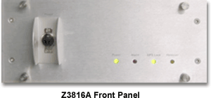
Four
LED
On-Off Switch
|
RS-232
|
10
MHZ, 19.6608 MHZ
|
Eight
|
User
Config.
|
MTI
260
|
27
VDC or 120 VAC
|

Z3816A
Main Board Connector Wiring
for both DC and 115VAC input versions
Z3816A power
supply pinout and typical readings data
Pins
numbered right to left, starting with pin 1:
(1&2)
Red: +5V
(3&4) Black: Gnd
(5) Yellow: +15V
(6) Black: N/C (no connection but DC version has a wire)
(7) Blue: -15V
(8) Purple: N/C
(9) Green: N/C
The
20-70VDC input version has corresponding pins and wires (one
to one correlation).
The
115VAC input version has 10 output pins -- all the connections
are the same except the -15V which is on pin 10 of the power
supply (the main board is, of course, the same as above.)
The
DC input version draws about 1.2A on the +15V at initial power
up due to the oven startup load. This drops to about 0.8A
after the oven reaches temperature. The 5V load is about 0.6A
and the -15V current load is not enough to register on a bench
supply meter.
(Thanks
to Gil Porter and Mitch Janoff.)
Download
Z3816A ROM binary dump here. (Use
HEX editor to read.)
Antenna
Alarm Problem on the Z3816A
A
frequent problem with this receiver is that some antennas
cause the internal antenna current alarm to activate. Although
the antenna is actually working, the receiver reports an error.
The Z8316 uses a Motorola M8 Oncore GPS receiver. This version
uses the antenna current info in the status word in the data
messages.
A simple work-around is to simply shunt the antenna connector
with an external resistor. Nominal values for antenna current
are between 15 and 80 mA. Values both under and over these
cause a under-current or over-current flagging, so the selected
resistor for current drawing should be chosen not to draw
more than 15mA so the alarm works if the antenna really becomes
open. 680 ohms seem to be a nominal value, but you may need
to adjust this depending upon your specific GPS antenna.
Have
trouble getting the Z3816A
to communicate on the serial port?
If
you have GPSCon software, please review the help file of
GPSCon under the section "Using the Z3816A". For those that
don't have this it is copied below.
GPSCon should automatically put the Z3816A into SCPI mode,
and take it out of full duplex mode, each time it is started.
This is not necessary for other models of receiver, but
the ID string cannot be examined until the receiver is in
SCPI mode. So GPSCon will examine the response to the *IDN
after having gone through the sequence of sending
PTIME:TCOD:CONT 0" and ":SYST:COMM:SER1:FDUP 0".
If the model is determined NOT to be a Z3816A, this fact
is flagged in the registry so subsequent starts will not
invoke the commands. If you wish to do this manually, procede
as follows: When the Z3816A is first used, it is possible
that it is in "time of day" (TOD) mode. To get it out of
this mode, press the "Stop" button. Then find the command
"PTIM:TCOD:CONT 0" in the drop-down list box. It will be
at the bottom of the list because it has no leading colon.
Press "Send" to issue the command.
The
second task is to ensure that the receiver is not in full
duplex mode. This is not essential but it does reduce the
amount of serial traffic. Find the command ":SYST:COMM:SER1:FDUP
0" and send it by pressing "Send". Hopefully the receiver
is now in a state where it can respond to normal commands
with the "scpi > " prompt. Press "Start" and the polling
sequence should commence.
Additional
notes by Craig McCartney, WA8DRZ