Prop
pitch style or custom antenna rotation motors need
an azimuth indicator and control. Typically, selsyns or simple
controls have been used for this purpose. In this article, K8CU
describes his custom design that uses an embedded controller
and touch screen LCD panel.
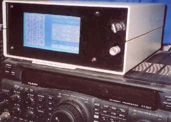
LCD Touch Screen Antenna Controller
Provides azimuth control for
antenna rotators; commercial, prop pitch or custom.
Fine direction resolution
Uses modern LCD graphics display
with integral touch panel
All electronic turns pulse
counter at rotor; easy motor interface
Works with any motor gear ratio
Small accessory-size enclosure
Many programmable options
Non-volatile memory retains
user settings
Serial interface for PC communication
Uses existing rotor power supply
This antenna controller
is the latest in a series of evolutionary controls I have used
for my antenna rotators. My earlier control methods included
simple hardware counters and LED direction controls.
These worked
but lacked refinement. I then designed a universal antenna direction
controller.
It has been in
use since 1994 and has worked well for me. It is an essential
station accessory, and a joy to use.
Circuit Description
This antenna rotor
control consists of:
-
Embedded micro-controller
-
Graphics LCD display
and touch screen matrix
-
Tower mounted
motor interface
This Hitachi or Zilog HD64180 embedded microcontroller runs at 12 MHz. Program memory is in an EPROM, and a Maxim RAM with internal battery maintains the data memory. Two serial ports are available, with either RS-232 or RS-485 supported.
A special purpose Seiko LSI controller provides LCD drive signals. This design has 64K of static RAM for LCD graphics. A hardware watchdog monitors the main CPU and generates a controller reset if an error condition develops.
I/O ports connected to the external interface use a board mounted connector.
Externally, two small relays for rotator direction control and a signal conditioner and optical isolator reside on the little interface board located near the main controller circuit board.
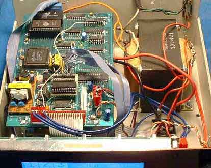
Inside the touch screen antenna rotor controller
x 
The graphics LCD
display mounts on the enclosure front panel. This display is
an attractive blue color, and the viewing angle and brightness
are excellent. It is internally illuminated by cold cathode
lamps that are driven by a high frequency lamp driver that is
located on the embedded controller circuit board. This LCD is
a graphics only display, and is organized as 256 wide by 128
pixels high. Immediately in front of this graphics array is
a unique touch screen circuit. It consists of a grid of nearly
invisible "wires" arranged as an X-Y matrix. Touching
the panel results in the "wires" making contact that
corresponds to the X-Y position of your finger.
A total of 64
separate touch locations are defined. There is no sound or physical
indication associated with this. When the LCD is turned off
and is not illuminated, a faint line can be seen where each
"wire" is located. During operation, nothing is visible
and it looks just like a normal LCD.
To implement a
front panel switch or control, the program draws LCD graphics
to surround a particular X-Y position where one of the "wire"
grids is located.This results in a clean front panel that is
easily customized for changing applications. Text or buttons
can be placed anywhere. This is a universal smart control panel,
customized by the software. The software is written in machine
assembly language, and all displays are bit mapped graphics.
The original commercial
application for this touch panel controller had the embedded
controller circuit board mounted directly behind the LCD panel.
The circuit board and LCD panel are about the same size, so
normally it's a neat package. The box I wanted to use wasn't
tall enough to allow this, so I remotely mounted the computer
board and attached the two together with some ribbon cables.
I also built a simple DC power supply adequate for my rotor
motor and placed it in the enclosure. Nothing gets hot so ventilation
isn't a problem.
Main Activity Screen
of the Direction Control
Front
panel controls are designed for simplicity. To turn the rotor
to 135 degrees, I enter 1 3 5 Go. The panel indicator
then displays the present direction as it changes and the selected
heading. To stop the rotation anytime, I press Stop. A fixed time
delay is built into the software to allow large antennas time
to completely stop before another directional change is allowed.
To use the control as a manual rotator, the Left and Right
Arrow buttons are used. Six preset headings named Australia,
Europe, Asia, Africa, etc. are available for
general antenna pointing. A
special Long Path button is pressed to turn the antenna
to the long path heading of the currently selected azimuth. A Setup button selects more screen menus for other functions. A real
time clock date and time display set for UTC is also shown on
the main activity screen.
Additional LCD screens
programmed into the controller allow for:
-
setting up the
specific motor gear reduction ratio
-
setting the time
and date of the internal real time clock
-
North or South
centered operation
-
specific antenna
directions for six common preset locations (Africa, Asia,
Europe, etc).
-
direction calibration
-
a full keyboard
screen is implemented


Click
on small screen for larger photo.
Motor Interface
I use this controller
with a prop pitch style rotor that turns my rotating tower and
antennas. The photograph shows the open motor with the protective
covering removed. The tower mounted motor interface consists
of a single transistor sized Hall effect component that sends
pulse information from the main motor shaft. One turn of the
high speed motor shaft sends one pulse to the controller located
inside the ham station. Small 3-conductor cable is all that
is necessary to add to the existing rotor wiring. I use common
"one pair with ground shield" audio cable. One wire
has five volts for power, one is ground, and the third is the
pulse signal.
A small magnet
is glued to a nut that is threaded onto the high speed motor
shaft. This magnet rotates past the Hall effect device, which
generates one pulse. The controller counts these pulses as a
method of knowing the angular distance traveled. Since real
motors coast after removal of power, the software keeps track
of this. The Hall Effect device is built into hardware store
small brass compression fittings and then covered with a potting
compound. This assembly fastens to a motor bolt with two set
screws.
The Hall Effect
switch need not be built inside the protective brass fittings
if it is securely mounted and protected. I chose this method
because it can be changed quickly as a complete assembly.
High resolution
antenna pointing is possible. The higher the motor ratio, the
greater the resolution. The motor ratio I use is 9576, and the
RTS rotating tower has a further two to one reduction, so the
total motor ratio is 19152 to one.
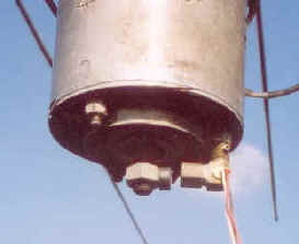
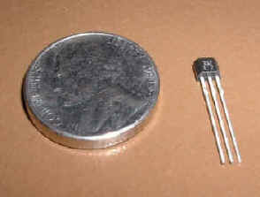
Magnet and Hall Effect Assembly
Hall Effect Device

The
newest part number now available for the sensor is Digikey #
480-5197-ND. I glued them inside a right angle brass compression
fitting and then mounted it to the motor end on a spare bolt
post. The magnet is glued to a nut that threads onto the high
speed motor shaft. This gives one pulse per motor revolution.
The assembled device is held to the prop-motor post by two small
Allen set screws. Works like a champ!
Rotators that will work
with this control:
It works where
access to the high speed motor shaft is available. The output
relays will directly connect across the two direction levers
or switches in an existing rotor control box. Some rotors like
the HyGain have a wedge brake that needs a separate control.
The brake needs to be activated before turning, and the brake
release needs to be delayed when rotation has stopped. This
controller has spare outputs, and the necessary software changes
to implement this wedge brake control are possible. A home made
or custom rotor1 should interface perfectly. This
control will work for any rotor if you can add a Hall effect
switch and a small magnet to the high speed motor shaft.
Multiple rotors
on separate towers using this single control box are possible
with a hardware and software upgrade.
Maintenance Issues
I have had trouble
from lightning strikes taking out the interface that fits directly
on the motor shaft. This costs a couple of dollars, and is not
hard to change. It has been replaced three times in eight years.
These are 5-volt Hall Effect switches sitting on the end of
a long control cable that acts like an antenna. The lightning
protection devices I have tried affected the output circuitry
of the Hall Effect switch, and prevented proper operation. I
use water-proof Molex connectors on this device to allow fast
exchange should the need arise. This signal line is optically
coupled at the station control end. This has prevented lightning
damage in the control box. The power leads going to the motor
also require lightning protection measures.
Adequate
protection of the Hall effect signal cable has proven necessary.
Suddenly, the antenna would rotate, but no signal direction
information was available. An inspection of the cable near the
tower base revealed the problem. Apparently one of the dogs
had been chewing on it!

Notes
1. Victor
Mozarowski, VE3AIA, "Turning That Big Array" , Ham
Radio Magazine, June, 1986. Pg. 10-15. This
is recommended reading as a basis for building a large rotor
at home. The control box and direction indicator are basic,
but the home builder needing a large rotor is presented with
an option to the prop pitch.